
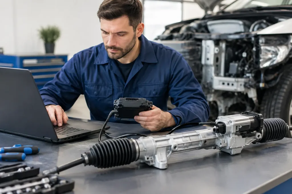
A replacement electric power steering rack can be mechanically correct, securely fitted and free from obvious faults, yet still leave warning lights on or steering assistance unavailable. The question often phrased as “how to prepare EPS coding” is therefore not just about connecting a diagnostic tool. It is about ensuring that the vehicle, replacement unit and workshop process are ready to communicate correctly.
EPS coding is vehicle-specific work. The exact procedure depends on the manufacturer, model year, steering system, diagnostic equipment and whether the rack is new, used, reconditioned, flashed or virginised. Preparing properly helps avoid repeat labour, misleading fault codes and a vehicle that drives poorly after the repair.
What EPS coding actually does
Electric power steering systems use a control unit to interpret signals from the steering torque sensor, vehicle speed sensors, steering-angle sensor and other control modules. It then commands the electric motor to provide the required level of assistance. The rack or column assembly may be configured with software, identification data and parameters that must match the vehicle.
Coding may write vehicle-specific configuration into the replacement unit. Depending on the application, the process can include programming, parameterisation, commissioning, end-stop learning, steering-angle calibration and clearing transport or replacement modes. These are related tasks, but they are not interchangeable.
For example, a rack may need flashing or virginising before it can accept a vehicle’s coding. A steering-angle sensor may need calibration after alignment. Fault memories may need clearing only after the underlying electrical or mechanical issue has been corrected. Treating all of this as a single “reset” can waste time and obscure the real cause of the problem.
How to prepare for EPS coding before fitting
Preparation starts before the old rack is removed. The most useful information is often still stored in the vehicle or the original steering control unit. A capable diagnostic scan should record all system fault codes, live data where relevant, the steering module part number, software details and vehicle identification information.
Confirm the fault and the correct repair route
An EPS warning message does not automatically mean the rack has failed. Low system voltage, corroded wiring, damaged connectors, CAN network faults, an implausible steering-angle signal or a failed battery management process can all affect steering assistance. On some vehicles, the steering control module is integrated into the rack; on others, it is part of the column or communicates with a separate module.
Accurate diagnosis is particularly important where a used or reconditioned unit is being considered. The replacement must be suitable for the exact vehicle application, including left or right hand drive configuration, motor position, mounting arrangement, electrical connections and electronic compatibility. A physically similar rack is not necessarily a compatible rack.
Where an existing unit has an internal mechanical or electronic defect, component-level reconditioning may be an appropriate solution. Where the control electronics are damaged beyond a viable repair, a replacement or dealer-supplied component may be necessary. The correct option depends on the fault, parts availability and the system’s coding requirements.
Record original vehicle and module information
Before disconnecting the original unit, retain as much relevant information as the diagnostic platform permits. This may include the VIN, coding string, parameter set, rack identification, software version and any adaptation values. Some manufacturers make these values available through guided diagnostic functions; others restrict programming access to approved systems or online accounts.
Do not assume that copying coding from one vehicle to another will work. A coding value can reflect brake system specification, driver-assistance equipment, wheelbase, suspension package, engine variant or market configuration. Incorrect parameterisation may create faults in the steering, stability-control or driver-assistance systems even if basic assistance appears to operate.
If the original module cannot communicate, obtain the correct technical information before fitting the replacement. This may mean confirming part numbers, checking manufacturer procedures or arranging programming through a specialist with the required diagnostic access.
Establish stable voltage and communication
Programming should never be attempted with an uncertain battery condition. EPS systems draw significant current, and control modules can be sensitive to voltage drops. Use an appropriate stabilised battery support unit, rather than relying on a battery that may already be weak after diagnostics, ignition cycling and workshop work.
Check that the diagnostic socket, relevant fuses, grounds and CAN communication are sound. Existing communication faults should be investigated before coding begins. If multiple modules are offline, or the vehicle has low-voltage history faults, coding the rack first may not resolve anything.
This is also the point to verify that the chosen diagnostic equipment can perform the required function. Generic scan tools are useful for reading faults and data, but not every tool can carry out manufacturer-level programming, security access or online parameterisation. In some cases, dealer involvement remains the practical route.
Complete the mechanical work correctly
Coding cannot compensate for poor mechanical installation. The steering wheel should be held in the straight-ahead position before the intermediate shaft is disconnected, following the manufacturer’s procedure. Care is needed to avoid damaging the clock spring or fitting the column shaft out of position.
The replacement rack must be centred correctly, with track rods set sensibly before final alignment. Electrical plugs should be clean, fully seated and checked for damaged terminals, water ingress or stretched wiring. Where applicable, inspect the subframe position and suspension components that could affect geometry.
A full wheel alignment is normally required after rack replacement. Steering-angle calibration should be carried out only when the vehicle is on level ground, tyre pressures are correct and wheel alignment has been completed to specification. Calibrating a sensor with the steering wheel off-centre can leave the car driving straight while its electronic systems believe otherwise.
A sensible EPS coding sequence
Once the vehicle is mechanically complete and electrically stable, follow the manufacturer-specific diagnostic routine. In broad terms, the process is to identify the replacement unit, complete programming or coding where required, erase only relevant stored faults, run guided initialisation functions and then calibrate the steering-angle sensor after alignment.
The order matters. Some systems will not accept steering-angle calibration until rack commissioning is complete. Others require the ignition to be cycled, the engine to run, or the steering wheel to be held at centre during a guided procedure. A road test may then be needed to confirm assistance, warning-light status, self-centring and straight-line behaviour.
During the final checks, look beyond the EPS warning lamp. Confirm that steering assistance changes naturally with vehicle speed, there is no notchiness or abnormal noise, and there are no new ABS, stability-control or driver-assistance warnings. Re-scan the vehicle after the road test to confirm that no relevant codes have returned.
When coding will not cure the fault
A successful coding message does not prove that every part of the steering system is healthy. Internal torque-sensor faults, motor defects, worn mechanical components, damaged wiring and intermittent network faults can remain after programming. Equally, a rack that will not code may have an incompatible module, incorrect software state, a power supply issue or a fault elsewhere on the vehicle network.
This is why fault codes should be interpreted in context. “No communication” can mean a failed control unit, but it can also indicate a blown fuse, poor ground, water-damaged connector or network issue. “Steering angle not initialised” may be a straightforward calibration requirement, or it may point to alignment, sensor or clock-spring concerns.
For vehicles with advanced driver-assistance systems, further calibration may be required after alignment or steering repairs. Requirements vary considerably by manufacturer and sensor layout, so this should be established before the vehicle is returned to service.
Preparing a reconditioned EPS rack
A properly prepared reconditioned rack can offer a practical alternative to complete new-unit replacement where the application and fault allow. The crucial point is that reconditioning, coding and calibration are separate stages of the overall repair. A rack can be rebuilt and workshop tested, then still require vehicle-specific programming once installed.
For applicable EPS models, Pro Power Steering can assess units at component level and may flash or virginise suitable racks in preparation for coding. This does not remove the need for correct installation, compatible diagnostic equipment or final calibration on the vehicle. It does, however, help fitting garages begin with a unit prepared for the correct next stage rather than an unknown electronic state.
The best preparation is not a universal checklist applied blindly. It is a vehicle-specific process: diagnose the original fault, confirm the part, preserve useful data, stabilise the electrical system, fit and align the rack correctly, then carry out the required coding and calibration. Done in that order, the repair has the best chance of restoring the smooth, precise and predictable steering the vehicle was designed to deliver.
